
 EN
EN
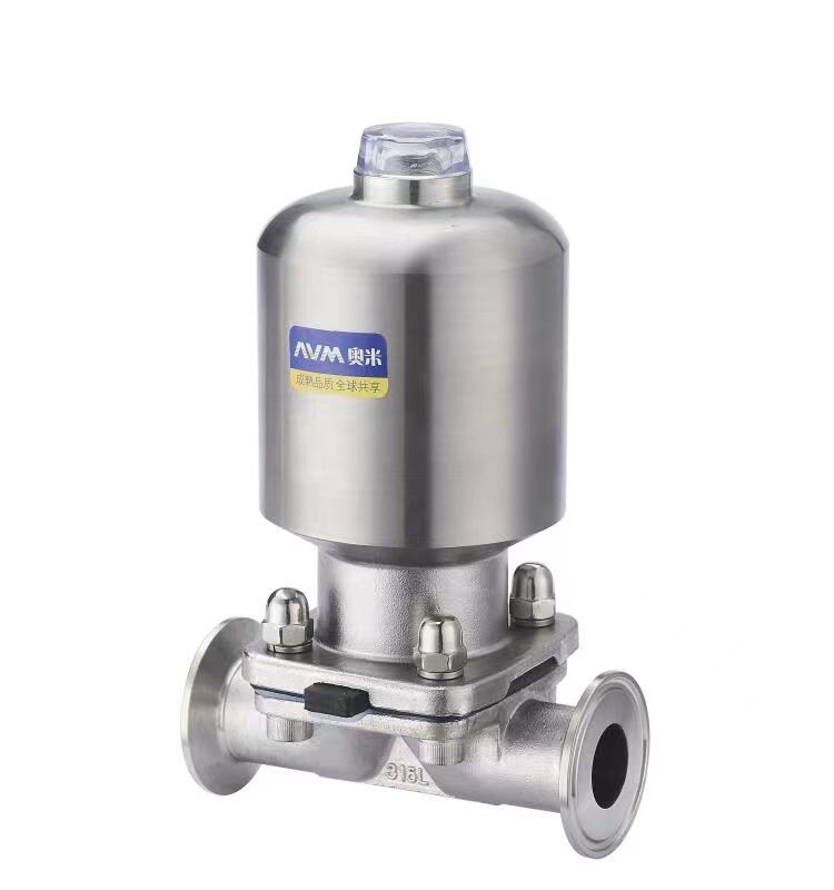
Thermal Cycling and Sterilization Stress on Diaphragm Valve Performance
How CIP/SIP Cycles Accelerate Elastomer Fatigue and Microcrack Formation in Diaphragm Valve Diaphragms
Repeated Clean-In-Place (CIP) and Steam-In-Place (SIP) cycles impose cumulative thermal stress that directly limits diaphragm valve service life. During SIP, elastomer diaphragms undergo rapid temperature excursions—from ambient to 121°C or higher—causing repeated expansion and contraction. This thermal shock generates microcracks at molecular boundaries, particularly in EPDM and other common elastomers. Each sterilization cycle subjects the diaphragm to thermal stress equivalent to 72 hours of continuous operation at peak temperature, accelerating fatigue far beyond normal use. Research shows EPDM diaphragms lose 40% of their expected service life after just 150 SIP cycles compared to non-sterilized applications. As microcracks propagate under mechanical actuation, containment integrity degrades—leading to leakage or failure. In pharmaceutical facilities performing daily SIP, diaphragm replacement frequency increases 2.5× versus non-sterile processes, confirming that thermal cycling—not just usage time—is the dominant factor governing maintenance planning.
Temperature Extremes (-40°C to +150°C) and Material-Specific Degradation: EPDM, PTFE-Lined, and Stainless-Steel-Reinforced Diaphragm Valve Diaphragms
Diaphragm performance varies significantly across temperature extremes, with degradation mechanisms tightly linked to material composition:
| Material Type | Optimal Range | Failure Mechanism | Degradation Rate at Extremes |
|---|---|---|---|
| EPDM Elastomer | -30°C to 130°C | Chain scission & compression set | 4× faster at 150°C |
| PTFE-Lined | -70°C to 200°C | Delamination & creep | 2× faster at -40°C |
| Stainless-Reinforced | -200°C to 260°C | Stress corrosion cracking | 3× faster at corrosive 150°C |
EPDM undergoes rapid oxidative degradation above 130°C, losing 60% of its tensile strength after 500 hours at 150°C. Below -30°C, it embrittles, increasing susceptibility to tearing during actuation. PTFE-lined diaphragms retain chemical inertness but suffer cold flow deformation at high temperatures—reducing clamping force and compromising seal integrity—and risk delamination when exposed to cryogenic conditions. Stainless-steel reinforced diaphragms offer the broadest thermal range but remain vulnerable to chloride-induced stress corrosion cracking in saline, high-temperature environments. Critically, thermal cycling between -40°C and +150°C creates differential expansion stresses that disproportionately affect multi-layer constructions; thermal fatigue accounts for 58% of premature failures in extreme-service applications, per industry reliability databases.
Diaphragm Material Selection for Optimal Diaphragm Valve Longevity
Chemical Compatibility Matrix: EPDM vs. PTFE-Lined vs. Metal-Reinforced Diaphragms Under Aggressive Process Media (Per ASTM D471)
Material selection is the single most decisive factor in maximizing diaphragm valve longevity. ASTM D471 provides standardized, reproducible testing for swelling, hardness change, and tensile retention—enabling objective comparison of chemical compatibility. The table below summarizes core performance attributes:
| Material | Chemical Resistance | Temperature Range | Flexibility | Typical Applications |
|---|---|---|---|---|
| EPDM | Excellent for acids, alkalis, ozone; poor for oils | –40°C to 150°C | High | Water, steam, mild chemicals |
| PTFE-lined | Nearly universal chemical inertness; resists solvents & oxidizers | –20°C to 230°C | Low; requires high actuation force | Pharma, biotech, aggressive acids |
| Metal-reinforced (e.g., stainless steel core with elastomer facing) | Excellent for corrosive fluids when combined with PTFE or FKM | Depends on facing; often –20°C to 200°C | Moderate; steel core adds structural rigidity | High-pressure steam, abrasive slurries |
EPDM delivers cost-effective performance in water-based systems but fails rapidly in hydrocarbon media due to swelling and loss of elasticity. PTFE-lined diaphragms are the gold standard for pharmaceutical applications where purity and chemical resistance are non-negotiable—even though their lower flexibility demands higher actuation energy. Metal-reinforced designs merge the durability of a rigid core with the sealing capability of an elastomeric or polymer facing, making them ideal for high-cycle, high-pressure, or abrasive service.
Impact of Abrasive Slurries and Corrosive Fluids on Wear Rates in Critical Diaphragm Valve Applications
Abrasive slurries and corrosive fluids degrade diaphragms through distinct yet often synergistic mechanisms. Silica-based slurries—common in mining and wastewater treatment—cause mechanical erosion at the contact surface, increasing wear rates by 300% relative to clean water service. When abrasion combines with chemical attack—as in mixed-acid slurries—the median service life drops by 50% within the first 1,000 cycles.
Corrosive fluids present a material trade-off: PTFE-lined diaphragms resist chemical degradation but lack resilience against abrasion and may develop pinholes under concentrated sulfuric acid at elevated temperatures. EPDM, while flexible and economical, swells irreversibly in oil-based slurries, leading to leakage. Successful long-term performance depends on matching the diaphragm’s primary resistance profile to the most aggressive component in the process stream—and supplementing with design features like metal reinforcement or predictive inspection intervals where warranted.
Mechanical Fatigue from Cycling Frequency and Diaphragm Valve Design
Weir vs. radial geometry: FEA evidence of stress concentration and its effect on diaphragm valve cycle life
Finite element analysis (FEA) consistently demonstrates that weir-type diaphragm valves concentrate stress at the sealing bead, where the diaphragm bends sharply over a raised dam. This localized bending induces high tensile and shear strains that accelerate elastomer fatigue. Radial-geometry valves, by contrast, distribute actuation forces more uniformly across the diaphragm surface—reducing peak strain by up to 30%, per published FEA studies. That reduction translates directly into extended service life: radial designs routinely achieve double the cycle count before failure compared to equivalent weir configurations. For high-availability processes requiring thousands of annual cycles—such as buffer preparation or media transfer in biomanufacturing—radial geometry is a proven, low-risk strategy to mitigate mechanical fatigue and extend maintenance intervals.
Operational thresholds: How >500 cycles/week reduces median diaphragm valve service life by 40%
Actuation frequency is a critical, often underestimated, driver of mechanical fatigue. Field data from pharmaceutical and bioprocessing facilities shows that exceeding 500 cycles per week reduces median diaphragm service life by ~40%. At this rate, the elastomer cannot fully recover between flex events, promoting early crack initiation and rapid propagation. For example, an EPDM diaphragm rated for 50,000 cycles under moderate duty may fail after only 30,000 cycles when operated at 600 cycles/week. To sustain reliability, operators should align valve selection with actual operational demand—either by implementing predictive maintenance based on cycle counting or specifying reinforced, high-cycle-optimized designs from the outset.
Common Failure Modes and Root Causes in Diaphragm Valve Diaphragms
Leakage, rupture, and tearing: Field data-driven breakdown of failure locations and underlying mechanisms
Diaphragm valve failures fall into three primary categories—leakage, rupture, and tearing—each tied to specific root causes and failure locations:
- Leakage most commonly originates at the perimeter seal, driven by microcrack formation from thermal cycling during CIP/SIP. These cracks compromise the sealing interface before visible damage appears.
- Rupture typically occurs at the dome, especially in PTFE-lined diaphragms operating near their upper temperature limit (e.g., >140°C), where pressure surges exceed the reduced yield strength of thermally degraded material.
- Tearing concentrates at the stem attachment point, where FEA reveals stress concentrations up to 300% higher than surrounding areas—making this region highly sensitive to both mechanical fatigue and improper installation torque.
Chemical exposure further accelerates failure: ethanol-based solvents reduce EPDM elasticity by over 50%, while calcium carbonate slurries cause measurable erosive wear in under 12 months. Crucially, field data indicates 70% of failures trace back to mismatched material selection—highlighting that proactive, application-specific material specification—not just reactive replacement—is the most effective way to reduce unplanned downtime. Implementing condition-based replacement aligned with these failure patterns cuts unscheduled outages by 65%.
FAQ
What are the main factors affecting diaphragm valve performance?
Key factors include thermal cycling during SIP/CIP, material degradation from temperature extremes, actuation frequency, and exposure to abrasive or corrosive fluids.
How can material selection impact diaphragm valve longevity?
Material compatibility with the process environment is critical. For instance, EPDM is suitable for water-based systems, while PTFE-lined diaphragms excel in chemically aggressive conditions. Selecting the proper material can significantly extend valve life.
Why do diaphragm valves fail under high cycling frequencies?
High cycling frequencies prevent elastomers from recovering between flex events, accelerating fatigue, crack propagation, and eventual failure.
What role does valve geometry play in cycle life?
Weir valves concentrate stress at the diaphragm’s sealing bead, while radial valves distribute forces uniformly. Radial configurations generally offer extended cycle life.
How can facilities reduce unplanned downtime for diaphragm valves?
Implementing condition-based replacement, predictive maintenance, and application-specific material selection can reduce downtime by up to 65%.
Table of Contents
- Thermal Cycling and Sterilization Stress on Diaphragm Valve Performance
- Diaphragm Material Selection for Optimal Diaphragm Valve Longevity
- Mechanical Fatigue from Cycling Frequency and Diaphragm Valve Design
- Common Failure Modes and Root Causes in Diaphragm Valve Diaphragms
-
FAQ
- What are the main factors affecting diaphragm valve performance?
- How can material selection impact diaphragm valve longevity?
- Why do diaphragm valves fail under high cycling frequencies?
- What role does valve geometry play in cycle life?
- How can facilities reduce unplanned downtime for diaphragm valves?