
Split Butterfly Valve Installation: Precision Alignment and Sealing
Flange Alignment and Bolt Tightening Sequence for Leak-Free Sealing
Getting those flange alignments right really matters if we want to avoid those pesky stress induced leaks in split butterfly valves. First things first, make sure those pipeline flange surfaces are spotless. Get rid of all that debris, mill scale stuff, and whatever old gasket material might still be hanging around. Any dirt or grime left behind will mess up the seal completely. When it comes time to line up the valve flanges with the rest of the piping system, don't just eyeball it. Most pros use either laser alignment tools or good old fashioned straight edge gauges. Check for parallelism too important that gap between flanges stays under half a millimeter. And let's not forget about making sure those bores actually match up in the center. A little extra attention here goes a long way toward keeping everything leak free down the road.
Apply a cross-pattern bolt tightening sequence in three progressive stages:
- Initial pass at 30% of the manufacturer’s specified torque
- Secondary pass at 70% torque
- Final pass at 100% torque, following the valve’s certified torque specification
This staged approach ensures uniform gasket compression, minimizes flange distortion, and preserves seat geometry. Field data from PEMA (2023) confirms that correct sequencing reduces leak incidents by 68% compared to radial or haphazard tightening methods.
Disc Swing Clearance Verification and Torque-Specific Bolt Tightening
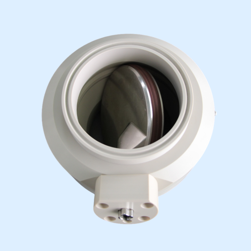
Before final bolting, verify disc swing clearance by manually rotating the valve through its full 0°–90° travel. Use calibrated feeler gauges to confirm a consistent 1–3 mm radial gap between the disc edge and body—critical for accommodating thermal expansion and preventing binding.
Always use traceable, calibrated torque wrenches and adhere strictly to valve-specific torque values:
| Bolt Size | Minimum Torque (Nm) | Maximum Torque (Nm) |
|---|---|---|
| M12 | 45 | 55 |
| M16 | 90 | 110 |
| M20 | 180 | 220 |
Over-torquing risks seat ring deformation and stem misalignment; under-torquing invites vibration-induced loosening and cyclic fatigue. After installation, perform a thermal swing test—operating the valve across its expected temperature range—to validate unrestricted disc movement under real-world conditions.
Flow-Aware Orientation and Performance Optimization
Flow Direction and Disc Closure Orientation: Impact on Performance and Debris Management
When installing split butterfly valves, it's important to position them so they close against the direction of flow. This setup actually works with the system rather than against it, as the fluid pressure helps push the valve shut tighter. What makes this arrangement so effective? The increased pressure improves sealing when closing, which means better shut off performance. Plus, particles get swept along with the flow instead of settling on the valve seat, creating a kind of self cleaning effect over time. Field data from years of operation shows installations following this orientation cut down unexpected maintenance needs by around 30 percent according to guidelines in ASME B16.34 Annex F. Plants that follow this practice tend to see fewer shutdowns for repairs and longer equipment life between services.
Conversely, installing the valve to close with the flow traps suspended solids against the disc-seat interface, accelerating abrasive wear and increasing leakage probability over time.
To further optimize performance:
- Position valves at least five pipe diameters downstream of elbows, tees, or pumps to avoid turbulent inflow
- Mount valves horizontally where possible to prevent gravitational settling of debris in the body cavity
- Avoid elevation changes immediately upstream that promote sediment deposition
These flow-aware practices collectively extend service life by up to 20% and lower system energy losses associated with flow resistance.
| Orientation Factor | Performance Impact | Debris Management Effect |
|---|---|---|
| Against flow | Enhanced seal pressure | Self-cleaning during closure |
| With flow | Premature seal degradation | Particle trapping |
| Turbulence avoidance | Consistent disc operation | Reduced abrasive wear |
Operational Commissioning and Actuator Integration for Reliable Control
Valve Disc Movement Verification and Actuator Travel Stop Settings
Commissioning begins with mechanical verification: rotate the disc manually from 0° to 90° to confirm smooth, obstruction-free travel. Then integrate the actuator and calibrate travel stops precisely—these limit over-rotation that stresses elastomeric seats and distorts disc alignment.
Hydraulic and pneumatic actuators require torque- and position-specific stop settings (e.g., 45 N·m ±5% for mid-size units), while modern smart actuators with HMI interfaces enable sub-degree angular control (±0.5°). Accurate stop calibration reduces mechanical failures during startup sequences by 37%, according to commissioning reports from the Valve Manufacturers Association (VMA).
Leak Inspection Protocols During Initial Pressure Testing
Validate seal integrity via a two-stage pressure test protocol aligned with ASME B16.104 and ANSI/FCI 91-1 standards:
- Hydrostatic test: Apply 1.5Ω maximum allowable working pressure (MAWP) for 30 minutes. Inspect flange joints, stem seals, and body seams using ultrasonic leak detectors. Document any weeping exceeding 2 drops/minute as noncompliant.
- Pneumatic test (required for gas/steam service): Conduct at 1.1Ω MAWP. Monitor for turbulent-flow leaks using acoustic emission sensors and record temperature-compensated pressure decay; deviations >0.5% over 15 minutes indicate compromised sealing.
Adherence to this tiered testing methodology reduces post-commissioning leaks by 63% compared to visual-only or single-stage verification.
Avoiding Common Split Butterfly Valve Installation Pitfalls
Misalignment-Induced Disc Binding and Field Correction Techniques
When it comes to disc binding problems in the field, flange misalignment is right at the top of the list as a cause. According to PEMA data from 2023, this issue accounts for around 20% of all operational failures. What happens when binding occurs? Well, it basically stops proper actuation and speeds up damage to components like seats and stems. To prevent these headaches, precision matters a lot. Make sure those flanges are parallel within about half a millimeter before starting to bolt everything together. Then follow the standard tightening procedure step by step: first apply 25% torque, then move to 50%, finally reaching full torque at 100%. And don't forget to check if the disc still rotates freely after each tightening stage. Small details like this can make a big difference in avoiding costly repairs down the road.
When misalignment is discovered post-installation, apply these proven correction techniques:
- Loosen all bolts and insert stainless steel shims between flanges to restore parallelism
- Use dial indicators mounted on the disc shaft to measure radial runout during partial rotation
- Re-torque progressively while monitoring disc friction with a digital torque screwdriver
In severe cases (flange deviation >2 mm), minor corrective grinding may be attempted—but replacement is strongly advised to maintain structural and sealing integrity. Final validation requires pressure testing to confirm leak rates remain below 0.1% of rated capacity under full operating conditions.
FAQ
-
Why is flange alignment important in split butterfly valve installation?
Proper flange alignment prevents stress-induced leaks by ensuring that the sealing surfaces are parallel, minimizing the risk of leaks. -
What is the recommended bolt tightening sequence for a split butterfly valve?
A staged cross-pattern tightening sequence is recommended: 30% torque for initial pass, 70% for second pass, and 100% for the final pass according to certified torque specifications. -
How do you verify disc swing clearance?
Manually rotate the valve disc through its full travel (0°–90°) and use calibrated feeler gauges to check the radial gap between the disc edge and the body. -
Why should split butterfly valves be installed to close against the flow direction?
Closing against flow improves sealing as fluid pressure helps close the valve tighter, enhancing shut-off performance and reducing maintenance needs. -
What are the common causes of disc binding in split butterfly valves?
Flange misalignment is a common cause of disc binding, leading to improper actuation and accelerated damage to valve components.