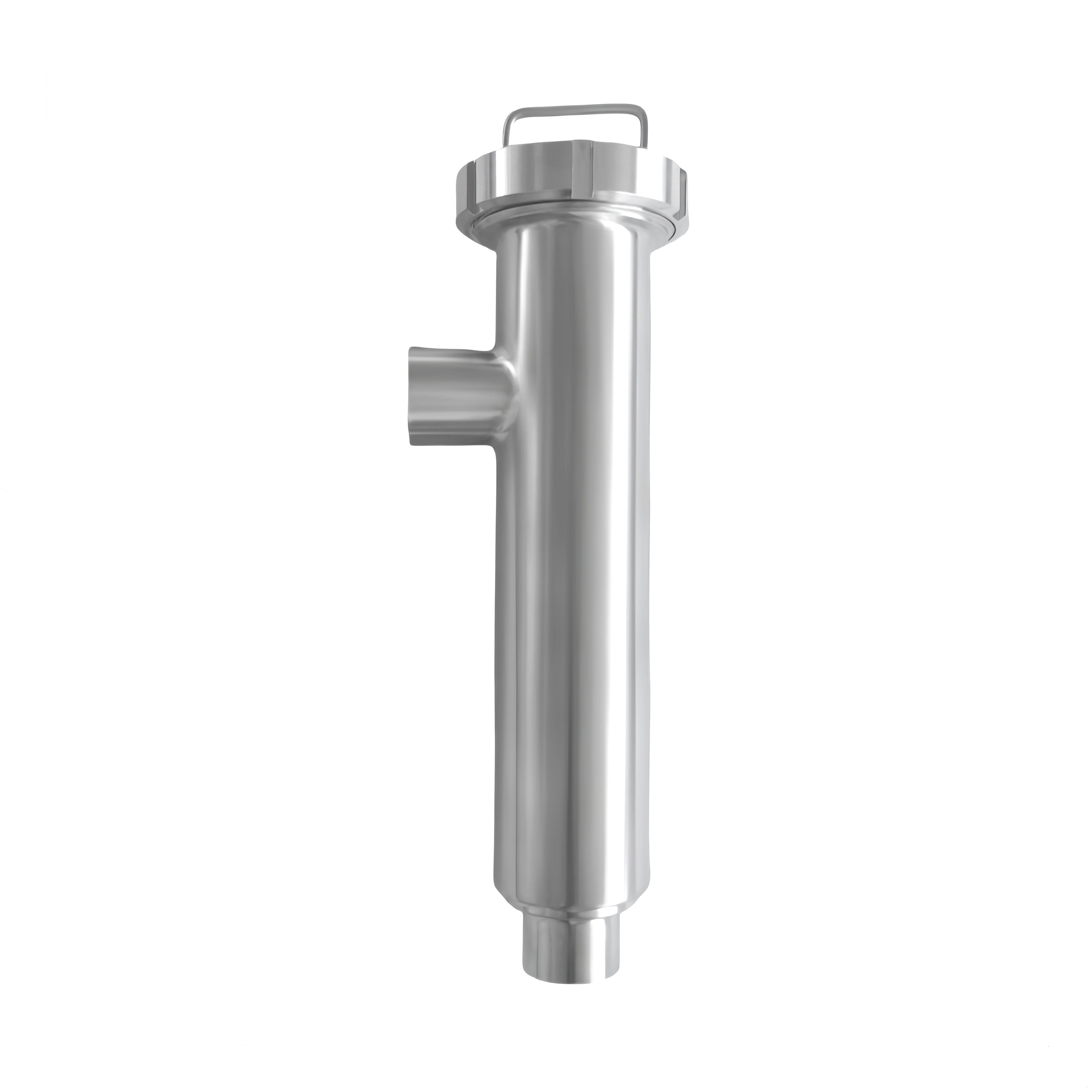

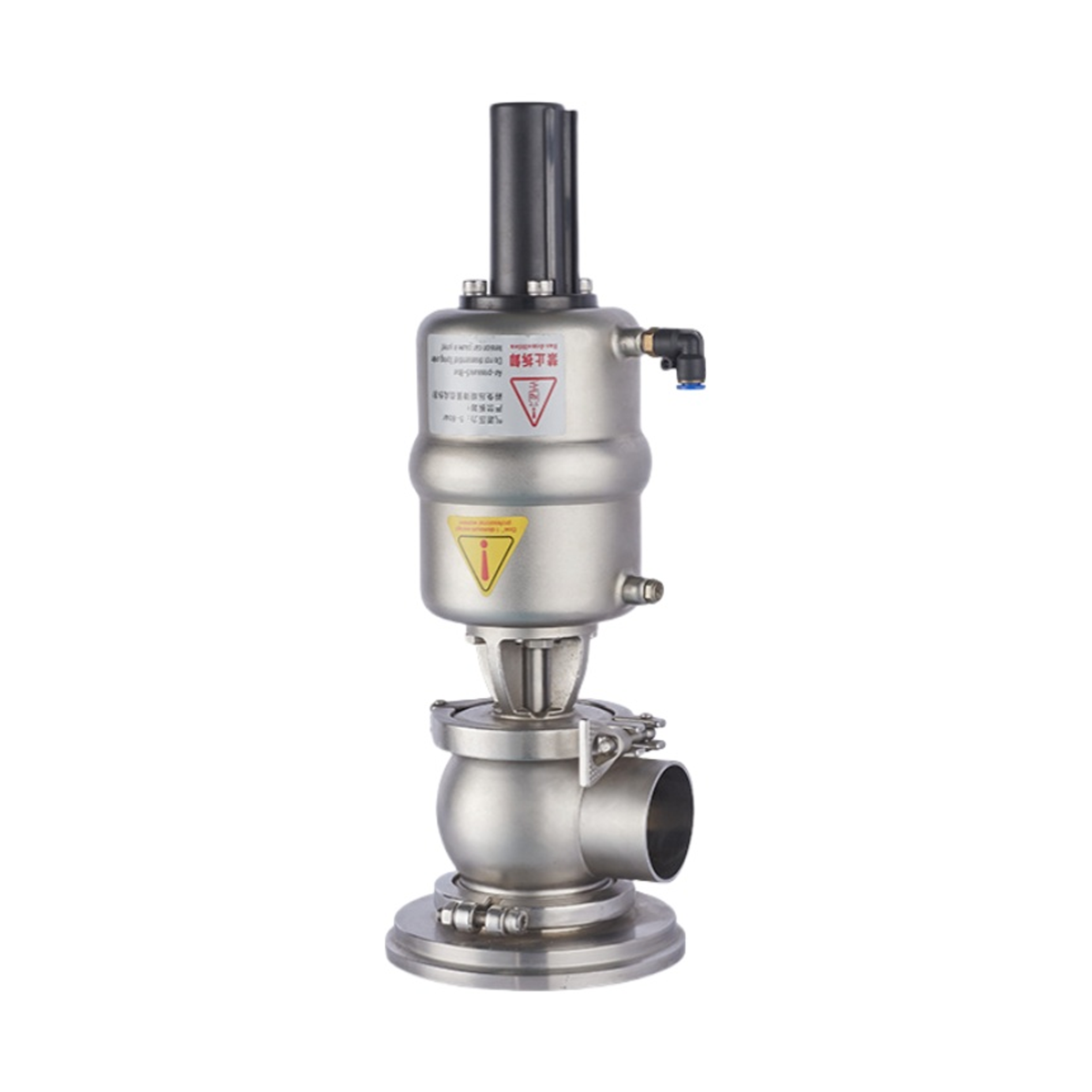

tank bottom valve
The GD3 Series Tank Bottom Valve is a high-performance, hygienic seat valve designed for reliable tank drainage in sanitary processing industries. With a compact structure, minimal moving parts, and metal-to-metal sealing, it ensures exceptional durability, low maintenance, and maximum cleanability. Available in both clamp-connected (GD3-T) and bolted (GD3-F) configurations, the valve supports 360° flexible installation and dead-leg-free flow, making it ideal for applications in pharmaceutical, dairy, beverage, and brewing operations. Fully CIP/SIP compatible and engineered to meet stringent hygiene standards, the GD3 valve is a dependable choice for modern hygienic process systems.
- Overview
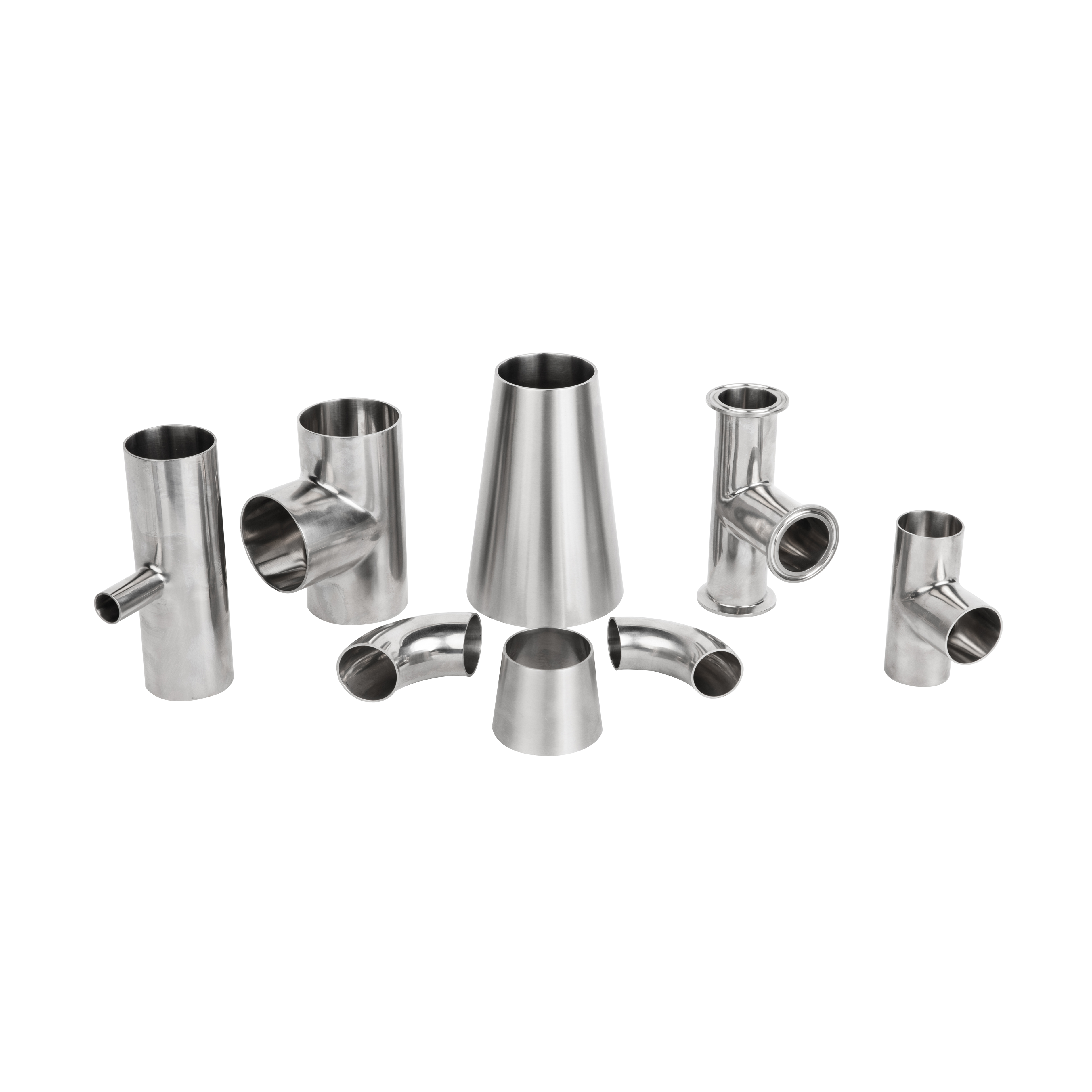
- Recommended Products
Detailed Description
GD3 Series Tank Bottom Valve – High-Performance, Hygienic Pneumatic Seat Valve
The GD3 Tank Bottom Valve is a high-performance, pneumatically actuated seat valve engineered for critical hygienic applications that require reliable drainage and cleanability at the base of process tanks. Based on a robust and proven single-seat valve platform, this valve features a compact, space-saving design with minimal moving parts, ensuring exceptional reliability, low maintenance, and long operational life.
It is ideal for sanitary industries such as brewing, dairy, beverage processing, and pharmaceutical manufacturing, where hygienic operation and ease of service are essential. Actuated remotely via compressed air, the GD3 valve consists of a valve unit and a tank bottom flange. To enhance seal longevity and minimize wear, the seal compression is achieved through precision-engineered metal-to-metal contact.
Available in Two Flexible Configurations:
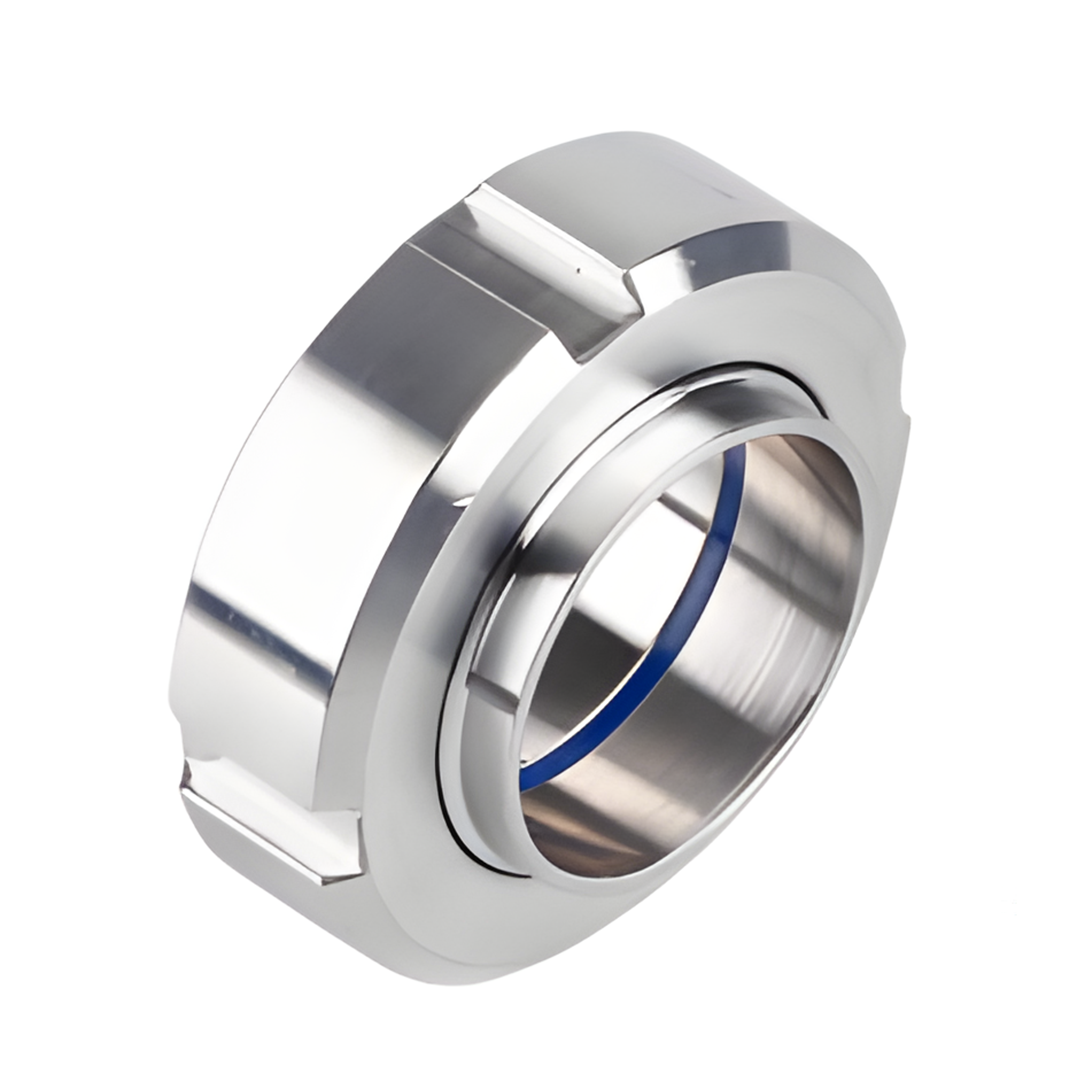
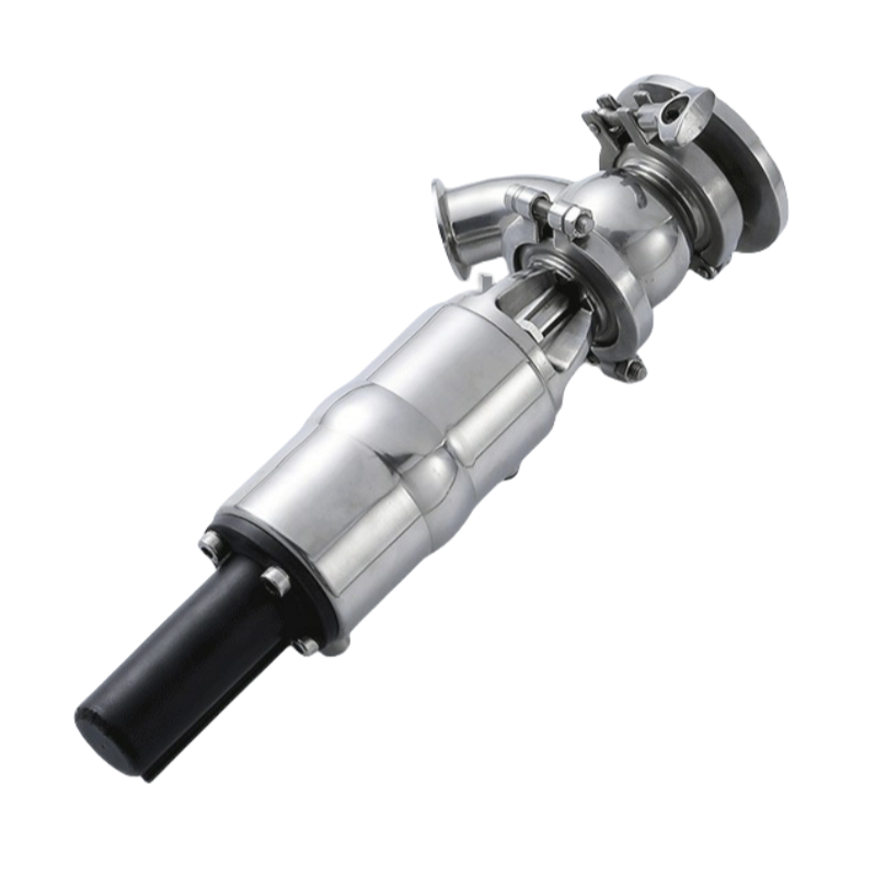
GD3-T Type – Clamp Connection
The GD3-T version features a clamp-type connection between the valve and tank flange. By slightly loosening the clamp, the valve body can be rotated to any position, enabling flexible alignment and easy maintenance access. The tank flange is directly welded to the tank, ensuring a hygienic and leak-free seal.
GD3-F Type – Bolted Connection
The GD3-F version utilizes a bolted connection, allowing for 360° rotation of the valve body for optimal positioning and installation flexibility. Like the T-type, its tank flange is permanently welded to the tank structure.
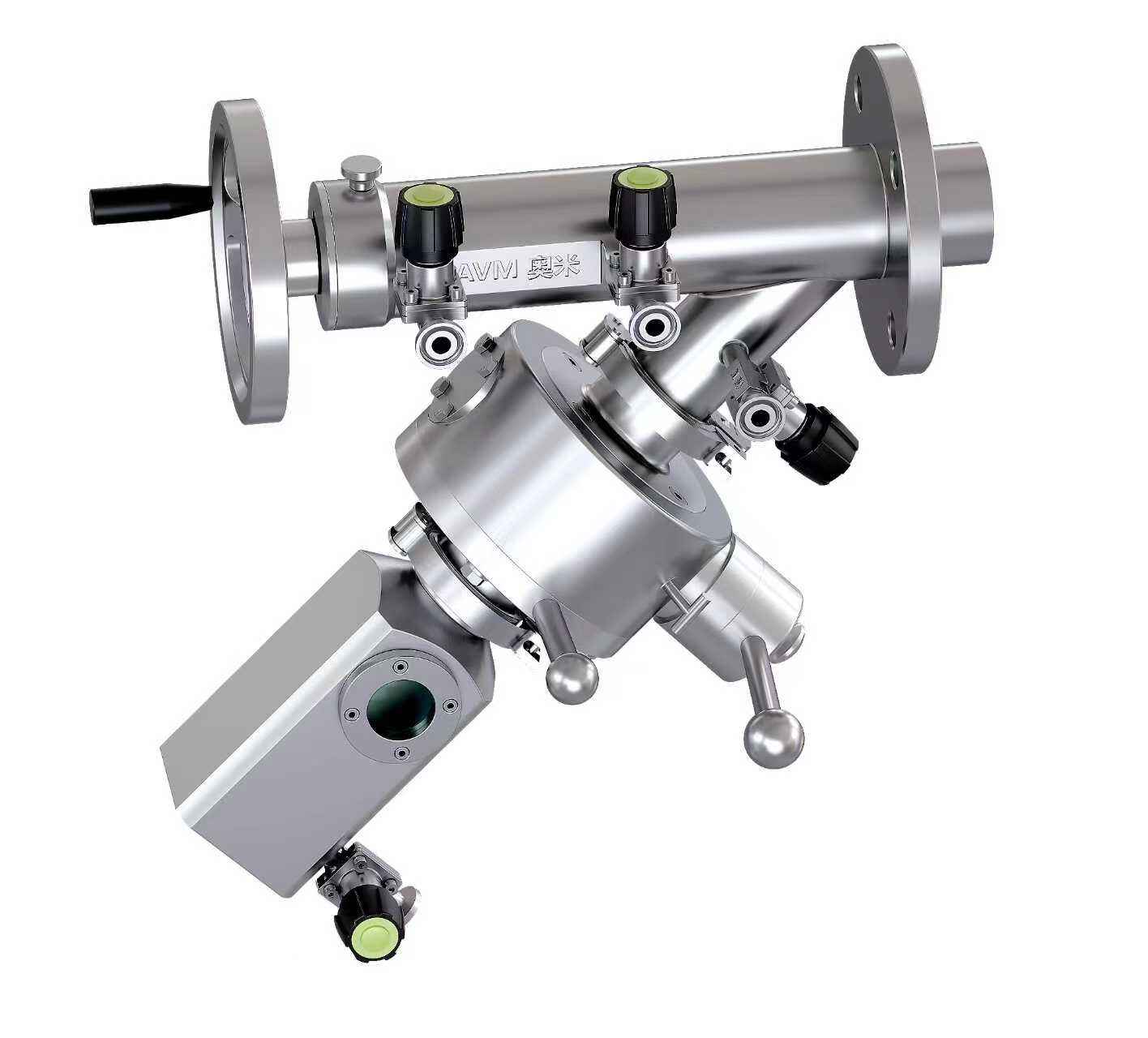
Both configurations offer dead-leg-free flow paths, full CIP/SIP compatibility, and are designed to support strict sanitary process environments. The GD3 valve is a versatile, maintenance-friendly, and automation-ready solution for modern clean-in-place and drain valve applications.
Parameter

| Technical data | |||
| Material | Contact product parts | 316L(1.4404) | |
| non-contact product parts | 304(1.4301) | ||
| Provide EN102043.1B certificate | |||
| Seal material | standard | EPDM | |
| All seal materil meet FDA 1772600 | |||
| option | NBR,FPM.Silicone | ||
| All seal materil meet FDA1772600 | |||
| Temperature | Running working temperature | -20~+135℃(EPDM) | |
| Sterilization temperature | 150℃(max 20min) | ||
| Pressure | Working pressure | 0~5bar(standard) | |
| Accepting high pressure requirement | |||
| Control air pressure | 5~8bar | ||
| Surface treatment | Internal surface | Ra≤0.8μm | |
| External surface | Grit blasting | ||
| Connection | Connection standard | welded end:DIN 11850 series2 | |
| welded end:INCH pipe standard | |||
| Connection method:welding.thread.clamp、flange | |||
| Option | Intligent controller | 24V DC | |
| 1/2 electromagnetism valve | |||
| Position sensor | 24V DC | ||
| 2 NPN/PNP position sensor | |||
| ‘More pressure required,pls contact with AOMI technical department. | |||

| dimensions(mm) | |||||||||
| DN | A | B | B1 | D | K | L | L1 | 0D | M(CLAMP) |
| DN25 | 35 | 289.8 | 298 | 145 | 91 | 55 | 20 | 29×1.5 | 21.5 |
| DN40 | 41 | 294 | 308 | 145 | 91 | 65 | 20 | 41×1.5 | 21.5 |
| DN50 | 48 | 326 | 345 | 165 | 130 | 80 | 30 | 53×1.5 | 21.5 |
| DN65 | 58 | 414 | 445 | 195 | 195 | 90 | 40 | 70×2.0 | 2B |
| DNB0 | 72 | 418 | 450 | 220 | 195 | 110 | 40 | 85×2.0 | 2B |
| DN100 | 82 | 432 | 463.5 | 250 | 195 | 120 | 40 | 104×2.0 | 2B |
| NCH | |||||||||
| 1.0° | 35 | 289 | 298 | 145 | 91 | 55 | 20 | 25.4×1.65 | 12.7 |
| 1.5' | 41 | 294 | 308 | 145 | 91 | 65 | 20 | 38.1×1.65 | 12.7 |
| 2.0° | 48 | 324 | 344 | 165 | 130 | 80 | 30 | 50.8×1.65 | 12.7 |
| 2.5' | 55 | 335 | 355 | 195 | 130 | 85 | 30 | 63.5×1.65 | 12.7 |
| 3.0° | 64 | 417.5 | 449 | 220 | 195 | 95 | 40 | 76.2×1.65 | 12.7 |
| 4.0° | 82 | 432 | 483.5 | 250 | 195 | 125 | 40 | 101.6×2.11 | 15.8 |
| M·Other connection method,please contact with AVM technical department. | |||||||||
| L1:depend on by pressure | |||||||||

| dimensions(mm) | |||||||||
| DN | A | B | B1 | D | K | L | L1* | OD | M(Clamp) |
| DN25 | 55.5 | 295 | 298 | 110 | 91 | 55 | 17 | 29×1.5 | 21.5 |
| DN40 | 65 | 301 | 310 | 120 | 91 | 65 | 20 | 41×1.5 | 21.5 |
| DN50 | 68.5 | 326 | 347 | 160 | 130 | 80 | 30 | 53×1.5 | 21.5 |
| DN65 | 84 | 414 | 445.5 | 180 | 195 | 90 | 40 | 70×2.0 | 28 |
| DNB0 | 87 | 418 | 450 | 180 | 195 | 110 | 40 | 85×2.0 | 28 |
| DN100 | 93 | 432 | 463.5 | 200 | 195 | 120 | 40 | 104×2.0 | 28 |
| INCH | |||||||||
| 1.0" | 55.5 | 295 | 298 | 110 | 91 | 55 | 17 | 25.4×1.65 | 12.7 |
| 1.5" | 65 | 301 | 310 | 60 | 91 | 65 | 20 | 38.1×1.65 | 12.7 |
| 2.0" | 68.5 | 325 | 346 | 160 | 130 | 80 | 30 | 50.8x1.65 | 12.7 |
| 2.5" | 80 | 335 | 356 | 160 | 130 | 85 | 30 | 63.5×1.65 | 12.7 |
| 3.0" | 84 | 417.5 | 449 | 180 | 195 | 95 | 40 | 76.2×1.65 | 12.7 |
| 4.0" | 93 | 432 | 463.5 | 200 | 195 | 120 | 40 | 101.6×2.11 | 15.8 |
| M*Other connection method,please contact with AVM technical department. | |||||||||
| L1*:depend on by pressure | |||||||||