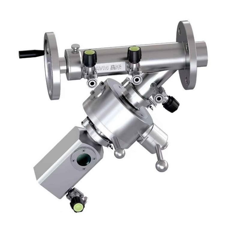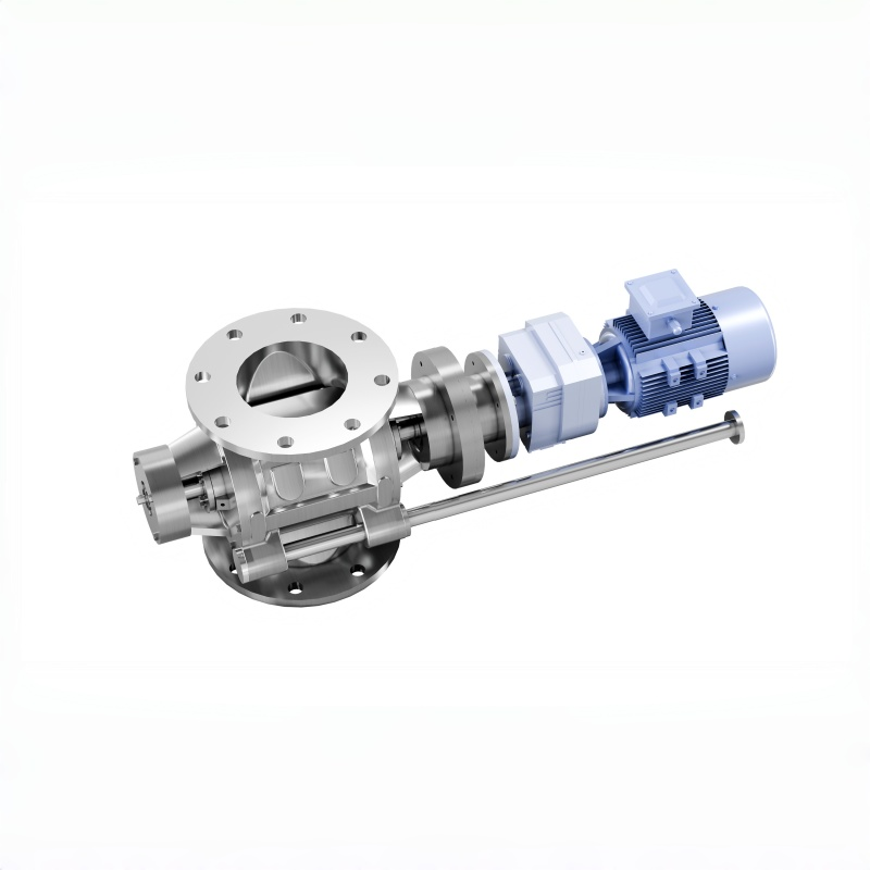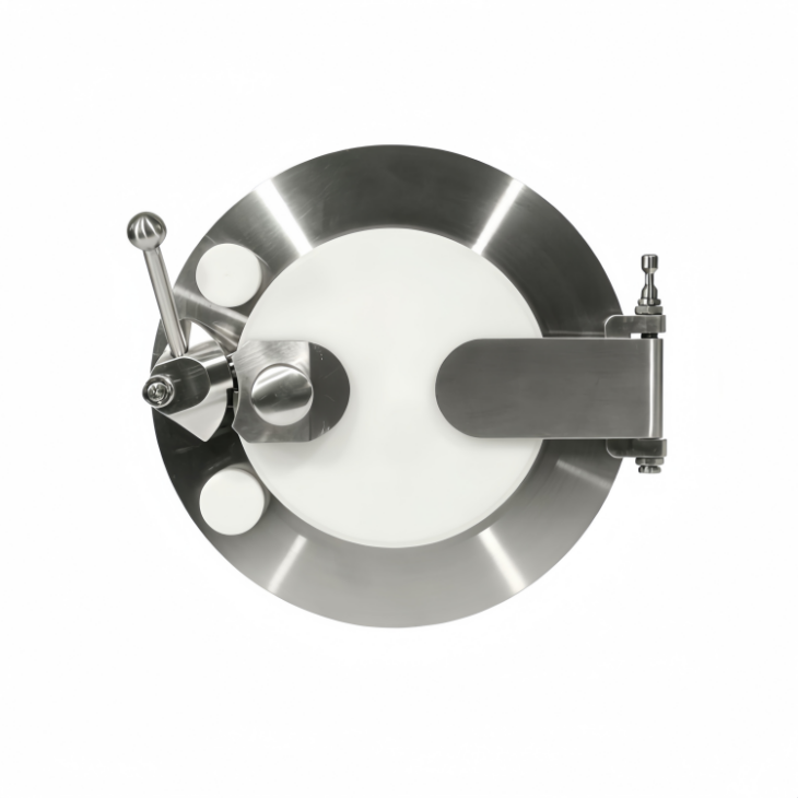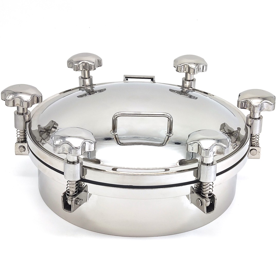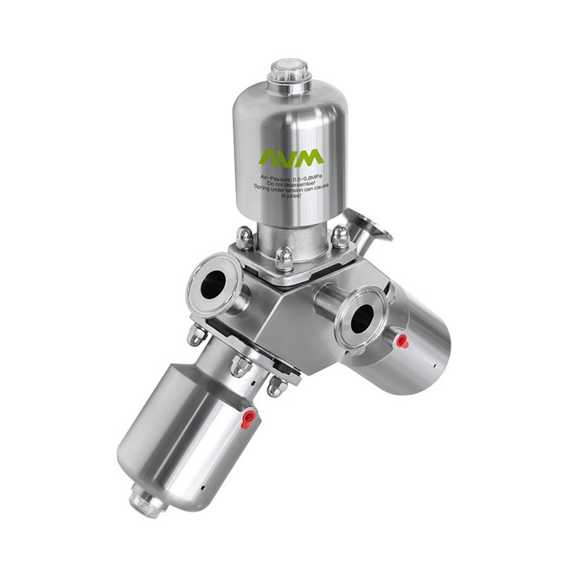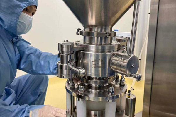


The Aseptic Mixproof Valve is a pneumatically operated, normally closed (NC) hygienic valve engineered for demanding applications where cross-contamination prevention and process reliability are critical.
Featuring a double-seat design with two independent seals on the valve disc, the valve creates a leakage chamber between the seals. In the event of seal wear or failure, any product leakage is automatically diverted to the chamber and safely discharged via a dedicated outlet—ensuring zero product mixing between different lines.
Hygienic operation: Ensures product purity in multi-line processing systems by preventing backflow and cross-contamination.
CIP-ready: The valve supports Clean-in-Place (CIP) cleaning without halting production, increasing system uptime and operational efficiency.
No product loss: Under normal conditions, the leakage chamber remains closed, maintaining a clean and controlled process environment.
Automation compatibility: The FH6/FH8 can be equipped with intelligent control heads from top automation brands such as Burkert, Alfa Laval, or GEMÜ. This enables remote actuation, real-time diagnostics, and sensor integration, supporting smart process control.
Ideal for the food and beverage, dairy, pharmaceutical, and personal care industries, this mix-proof valve delivers exceptional reliability, cleanability, and compliance with hygienic standards.


① Valve Position: CLOSED
Control air pressure: 0 bar at connection L1 (main stroke)
Control air pressure: 0 bar at connection L2 (upper valve disc stroke)
Control air pressure: 0 bar at connection L3 (lower valve disc stroke)
Separation of two different media is ensured.
In case of leakage, the product will be discharged outward through the leakage chamber under depressurized conditions.
② Valve Position: OPEN
Control air pressure: 6 bar at connection L1 (main stroke)
The bottom valve disc lifts, closing the leakage chamber.
Both valve discs are in the open position.
The upper and lower valve discs are fully opened relative to each other, allowing product flow.

③ Cleaning the Upper Valve Seat
Control air pressure: 6 bar at connection L2 (upper valve disc stroke)
During the cleaning process, the top valve disc is lifted with an adjustable stroke (pulse stroke should be set appropriately).
The valve seat, valve disc seals, clearance areas, and leakage exhaust pipe are thoroughly cleaned.
④Cleaning of the lower seat via valve housing. Control air pressure of 6 bar at connection L3. The bottom valve disk is lifted during the cleaning procedure. The valve seat, valve disk seals, and clearance, as well as the leakage exhaust pipe, are thoroughly cleaned.

①Valve position: CLOSED
Control air pressure: 0 bar
Connection: Separation of two hostile media
Leakage (if any): Guided outward through the leakage chamber in a depressurized state.

Control Air Pressure: 6 bar at connection L
The bottom valve disk lifts, closing the leakage chamber.
Both valve disks are in the "open" position.
The upper and lower valve seats are open, allowing flow between the two lines.

①Internal Leakage Drainage
Control air pressure: 0 bar at connection L1 (main stroke)
Control air pressure: 0 bar at connection L2 (upper valve disk stroke)
Control air pressure: 0 bar at connection L3 (lower valve disk stroke)
The two different media are separated.
Any leakage, if it occurs, is drained outward through the leakage chamber in a depressurized state.

②Valve Status: Open
Control Air Pressure: 6 bar at connection L1
The bottom valve disk lifts and closes the leakage chamber.
Both valve disks are in the "open" position.
The top and bottom flow paths are open and connected to each other.
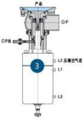
③Washing the Leakage Cavity of Pipe and Valve
Control air pressure: 6 bar at connection L2
During the cleaning process, the top valve disk is lifted with an adjustable stroke (pulse)
Set the stroke according to the cleaning requirements
The valve seat, valve disk seals, clearance area, and the leakage/exhaust pipe are all effectively cleaned
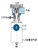
④Washing the Leakage Cavity of Tank and Valve
Control air pressure: 6 bar at connection L3
During the cleaning process, the bottom valve disk is lifted
The valve seat, valve disk seals, clearance area, and the leakage/exhaust pipe are thoroughly cleaned
AVM double seat valve matrix ensures compliance with factory sanitary and aseptic requirements.
The factory is capable of establishing fully automated, multi-way valve systems.
The valve matrix supports efficient operation of modern production processes and CIP/SIP cleaning cycles, maximizing workshop utilization and optimizing cost efficiency.
Double seat valves ensure reliable product separation and prevent cross-contamination.
Please refer to the photo for details.
| Material | Contaot product parts | 316L(1.4404) |
| non-contact product parts | 304(1.4301) | |
| Provide EN 102043.1B certificate | ||
| Seal material | Standard | EPDM |
| Option | NBR\FPMSilicone | |
| All seal materals comply wih FDA 177.2600 | ||
| Temperature | Running working temperature | -20~+135℃(EPDM) |
| Sterillzation temperature | 150℃(Max 20min) | |
| Pressure | Working pressure | 0-5bar |
| Accepting high pressure requirement | ||
| Control air pressure | 6~8bar | |
| Surface treatment | Internal surface | Ra≤0.8μm |
| External surface | Grit blasting | |
| Connection | Connection standard | welded end:DIN 11850 series2 |
| welded ond:INCH pipe standard | ||
| Connection method:welding、thread、clamp、flange | ||
| Option | Inteligont controlor | 24V DC |
| 1/3 electromagnetism valve | ||
| Position sonsor | 24V DC | |
| 2/3/4 NPN/PNP position sensor | ||


| dimensions(mm) | ||||||||||
| DN | A | B | L | L1 | D | H | S | DN | Stroke(K) | M(DIN) |
| DN40 | 350.5 | 90 | 60 | 65 | 89 | 8 | 29*1.5 | 41×1.5 | 23 | 21.5 |
| DN50 | 384.1 | 103B | 74.5 | 85 | 123 | B | 29*1.5 | 53x1.5 | 30 | 21.5 |
| DN65 | 392.8 | 1135 | 91.5 | 100 | 123 | B | 41*1.5 | 70×2.0 | 36.5 | 28 |
| DNB0 | 523.5 | 138 | 108 | 120 | 179 | 8 | 70*2.0 | 85*2.0 | 47.5 | 28 |
| DN100 | 533 | 152 | 127 | 150 | 173 | 8 | 85*2.0 | 104*2.0 | 47.5 | 28 |
| 3A | ||||||||||
| 1.5° | 349 | 90 | 56.8 | 65 | 89 | B | 291.5 | 38.1×1.65 | 23 | 12.7 |
| 2.0' | 382.8 | 103.B | 72 | 85 | 123 | B | 29*1.5 | 50.8*1.65 | 30 | 12.7 |
| 2.5' | 389.2 | 117 | 86 | 100 | 123 | 8 | 41*1.5 | 63.5×1.65 | 36.5 | 12.7 |
| 3.0' | 519.5 | 125 | 99.9 | 110 | 173 | 8 | 53*1.5 | 76.2*1.65 | 42 | 12.7 |
| 4.0° | 531 | 152 | 124.4 | 150 | 173 | B | 85*2.0 | 101.6*2.11 | 47.5 | 15.8 |

| dimensions(mm) | ||||||||
| DN | A | L | L1 | D | S | K | DN | Stoke(K) |
| DN40 | 350.5 | 59.5 | 65 | 83 | 140 | 65 | 41×1.5 | 23 |
| DN50 | 384.1 | 68.5 | 85 | 123 | 160 | 80 | 53×1.5 | 30 |
| DN65 | 392.2 | 83 | 100 | 123 | 180 | 80 | 70×2.0 | 36.5 |
| DNBO | 523.5 | 90 | 120 | 173 | 200 | 100 | 85*2.0 | 47.5 |
| DN100 | 533 | 95.5 | 150 | 173 | 220 | 100 | 104*2.0 | 47.5 |
| 3A | ||||||||
| 1.5° | 348 | 58 | 65 | 83 | 140 | 65 | 38.1×1.65 | 23 |
| 2.0° | 382.8 | 67 | 85 | 123 | 160 | 80 | 50.8*1.65 | 30 |
| 2.5° | 389.2 | 76 | 100 | 123 | 180 | B0 | 63.5x1.65 | 36.5 |
| 3.0° | 519.5 | B8 | 110 | 173 | 200 | 100 | 76.2*1.65 | 42 |
| 4.0° | 591 | 99.5 | 150 | 179 | 220 | 100 | 101.62.11 | 47.5 |

| dimensions(mm) | ||||||||||
| DN | A | B | L | L1 | D | H | S | DN | Stroke(K) | M(DIN clamp) |
| DN40 | 350.5 | 90 | 60 | 65 | 89 | 8 | 2971.5 | 41×1.5 | 23 | 21.5 |
| DN50 | 384.1 | 103.B | 74.5 | 85 | 123 | 8 | 29*1.5 | 53x1.5 | 30 | 21.5 |
| DNE5 | 3928 | 113.5 | 91.5 | 100 | 123 | 8 | 41*1.5 | 70×2.0 | 36.5 | 28 |
| DN80 | 523.5 | 138 | 108 | 120 | 173 | 8 | 70*2.0 | 85*2.0 | 47.5 | 28 |
| DN100 | 533 | 152 | 127 | 150 | 173 | 8 | 85*2.0 | 104*2.0 | 47.5 | 28 |
| 3A | ||||||||||
| 1.5° | 349 | 900 | 56.8 | 65 | B9 | 8 | 29*1.5 | 38.1×1.65 | 23 | 12.7 |
| 2.0° | 382.8 | 103.8 | 72 | 85 | 123 | 8 | 291.5 | 50.8*1.65 | 30 | 12.7 |
| 2.5° | 389.2 | 117 | 86 | 100 | 123 | 8 | 41*1.5 | 63.5x1.65 | 36.5 | 12.7 |
| 3.0° | 519.5 | 125 | 99.9 | 110 | 173 | 8 | 53*1.5 | 76.2*1.65 | 42 | 12.7 |
| 4.0° | 531 | 152 | 124.4 | 150 | 173 | 8 | 85*2.0 | 101.6*2.11 | 47.5 | 15.8 |
The DZ4 Aseptic Mixproof Valve is a pneumatically actuated seat valve featuring a hygienic and flexible design, based on a proven single-seat valve platform. It is specifically designed for processes where two different liquids flow through the same valve simultaneously. The valve not only prevents cross-contamination between fluids but also allows for easy monitoring of its operation. It is widely used in the dairy, beverage, pharmaceutical, and other hygienic industries.
The DZ4 valve is operated remotely using compressed air and is normally closed (NC) in its default state. It is equipped with two mini-type, normally open pneumatic valves — one serves as a drain valve and the other as a cleaning valve for CIP (Clean-in-Place) applications.
The valve stem is designed with two sealing rings, which create a leakage chamber between them. In the event of internal leakage, the product flows into the leakage chamber and is discharged through the drain valve. Before opening the main valve, the leakage chamber can be cleaned to ensure hygienic and safe operation.

| Material | Contact product parts | 316L(1.4404) |
| non-contact product parts | 304(1.4301) | |
| Provide EN 102043.1B certificate | ||
| Seal material | Standard | EPDM |
| Option | NBR、FPM、Silicone | |
| All seal materials comply with FDA 177.2600 | ||
| Temperature | Running working temperature | -20-+135℃(EPDM) |
| Sterilization temperature | 150℃(Max 20min) | |
| Pressure | Working pressure | 0-5bar(standard) |
| Accepting high pressure requirement | ||
| Control air pressure | 5~8bar | |
| Surface treatment | Interna surface | Ra≤0.8μm |
| External surface | Grit blasting | |
| Connection | Connection standard | welded end:DIN 11850 series2 |
| welded end:INCH pipe standard | ||
| Connection method:welding、thread、clamp、flange | ||
| Option | Inteligent controller | 24V DC |
| 1/2 electromagnetism valve | ||
| Position sensor | 24V DC | |
| 2 NPN/PNPposition sensor | ||

| DN | B | H | K | C | L | β | D | M(DIN clamp) |
| DN40 | 296 | 109 | 90 | 25.2 | 65 | 30° | 41×1.5 | 21.5 |
| DN50 | 325.5 | 115 | 130 | 25.2 | 85 | 30° | 53×1.5 | 21.5 |
| DN65 | 352 | 128 | 130 | 25.2 | 90 | 30° | 70×2.0 | 28 |
| DNBO | 422 | 137.5 | 195 | 25.2 | 110 | 30° | 85*2.0 | 28 |
| DN100 | 431 | 142.5 | 195 | 25.2 | 130 | 30° | 104*2.0 | 28 |
| INCH | B | H | K | C | L | β | OD | M(3A clamp) |
| 1.5° | 296 | 109 | 90 | 25.2 | 65 | 30° | 38.1×1.65 | 12.7 |
| 2.0° | 325.5 | 115 | 130 | 25.2 | 85 | 30° | 50.8*1.65 | 12.7 |
| 2.5' | 331 | 122.5 | 130 | 25.2 | 90 | 30° | 63.5×1.65 | 12.7 |
| 3.0° | 418.5 | 130 | 195 | 25.2 | 100 | 30° | 76.2*1.65 | 12.7 |
| 4.0° | 431 | 142.5 | 195 | 25.2 | 130 | 30° | 101.62.11 | 15.8 |
Address
No. 373 Oufan Road, Dongtou District, Wenzhou City, Zhejiang Province, China.
Tel